Start your project
You must use ours design template to create your design.
After downloading the templates, open with AutoCAD or DraftSight the format you prefer, as if it were a normal template.
You can design for laser cutting in one of five different material formats:
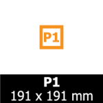
P1
useful size:
181 x 181 mm
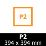
P2
useful size:
384 x 384 mm
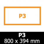
P3
useful size:
790 x 384 mm
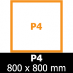
P4
useful size:
790 x 790 mm
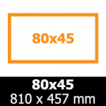
80×45
useful size:
800 x 450 mm
available only for
felt and cardboard
How to draw for the laser
The color used for the drawn lines determines what the laser will do, whether it is a cut or an engraving.
For example, if you're designing a little bird with a blue outline, the laser will cut a little bird ...

If you convert the same lines in red, the laser will engrave the bird on the chosen material, and so on.
It's that easy!
Now let's get to the details ...
How our templates work for AutoCad
Templates are in millimeters and in 1: 1 scale.
The layers are already set with the colors and the correct thickness of the tracks to "communicate" with the laser. To draw a shape to be cropped it is therefore sufficient to make the CUTTING layer current and draw on this layer. To add a vector engraving it will be necessary to draw on the corresponding layer.
The template is indicated by two orange perimeters: The external perimeter corresponds to the actual format of the material plate; the innermost perimeter corresponds to the area actually used for laser cutting.

All elements, cutting lines or incisions must be inscribed within the smallest perimeter.
The layer 0 is blocked: this layer contains the template and it is not possible to insert other elements. DO NOT CANCEL the orange template before uploading the file!
The orange lines are ignored by the laser and at the time of calculating the production cost, they simply serve as a reference.
Cutting lines
The basic part of your design are the shapes you will cut.
The simplest way to visualize how this will turn into your project is to imagine placing on a sheet of paper the pieces you would like to make, and then draw their outline on the sheet with a pencil. Your file should remember that sheet with the lines drawn.
To obtain a cutting line, draw lines and shapes on the CUTTING layer.

The properties of the layer are already set: color BLUE (RGB values 0,0,255) and line thickness 0,00.
Engraving of vector lines
The vector etching process is very similar to the cutting method, but instead of piercing the material, the laser only affects the surface.
The laser will move along the engraving lines in your drawing. There are three different levels of engraving available: light, medium and deep, each with a different intensity and therefore depth. All three incisions are drawn very precisely with subtle lines, roughly the same size as the laser beam.
Light vector engraving
Draw lines and shapes on the layer LIGHT of color magenta.

The properties of the layer are already set: magenta color (RGB 255, 0, 255) and thickness of the line 0,00mm.
Vector media engraving
Draw lines and shapes on the layer AVERAGE of color green.

The properties of the layer are already set: green (RGB 0, 255, 0) and thickness of the line 0,00mm.
Deep vector engraving
Draw lines and shapes on the layer DEEP Red.

The properties of the layer are already set: red (RGB 255, 0, 0) and thickness of the line 0,00mm.
Engraving of raster fills
WARNING! Autocad unfortunately, badly handles the fills applied to curved paths. In fact, the filled paths are generated as open paths, and even if when viewed in Autocad they appear without problems, in reality it is not possible to engrave them to the laser.

Our making system is able to recognize fills with open paths and therefore not accept the file. If you encounter this problem, we recommend that you export the file as Autocad DXF R13 and lay out it on our templates for Inkscape (opensource software freely downloadable), combining the correct fills and then removing the orange traces of the raster and 0 layers.
Generally the incisions of raster fills are used for areas with backgrounds.
We do not recommend engraving elements that are smaller than 0.5mm in raster mode: it will not lead to good results.
The scale of the raster engraving goes from the black that corresponds to the most marked incision, up to the very light gray that will make the engraving lighter (or white, which corresponds to the null incision). You can use any grayscale between the two extremes, but remember that the three RGB values must be equivalent. Make sure you use solid and spot colors and no patterns or textures.
To obtain a more defined border in an area engraved with a raster pattern, combine the black or gray fill with a track corresponding to a vector engraving.
The Raster layer
The Raster layer is set to have an orange color (RGB 246, 146, 30): our making system ignores this color, so the orange lines will not be calculated at the time of the quote and the laser will ignore them at the time of production.
The orange lines only serve to delimit the boundaries within which the fill should be inserted to create the raster engraving.
Engraving of light raster fills
For AutoCAD
Draw a closed shape on the Raster layer.

Use the Hatch command (H) and select the inside of the shape in which to insert the raster fill.
Choose from the fill type drop down menu solids to create a uniform fill (patterns are not allowed).

Choose from the fill color menu Select color.

click on the section True Color. Enter as a value RGB 230, 230, 230.


For DraftSight
Draw a closed shape on the Raster layer or on one of the other vector engraving layers.
Choose from the menu Drawing > Hatch / Fill and select the mode Filling
Choose the option A color and set the dark / light slider on 50: in this way you will get a single uniform color
Set the color, black or gray, by clicking on the button … . Enter the values shown below for raster engravings in the RGB fields (light raster engraving = 230,230,230; average raster engraving = 128,128,128; deep raster engraving = 0,0,0)
The color setup window should look like this:

Once the color is set click on the button Specify objects and select the objects to match the fill.
Engraving of medium raster fills
Draw a closed shape on the Raster layer and select a uniform fill, as explained above.
Choose from the fill color menu the color 8 , or specify the color in the mode True Color: the values are RGB 128, 128, 128.

Engraving of deep raster fills
Draw a closed shape on the Raster layer and select a uniform fill, as explained above.
Choose from the Select colors> fill color menu 250 , or specify the color in the mode True Color: the values are RGB 0, 0, 0.

It is obviously possible to combine raster engravings with vectorial engravings: in practice, the laser will first create an area in raster mode, and then draw a contour. Simply combine a solid fill with the Hatch command to an element of any layer.
For example, a light gray fill (light raster) to an element of the deep vector engraving layer:

To use the text
All the texts inserted in your drawing must be converted into outlines. In this way the laser will follow your drawing correctly, even without having the same installed font.
Once you have turned the text into tracks you will not be able to edit it, so do this after checking the spelling!
You can move the text on the layer to create the effect you prefer: with fills for raster engravings, lines for vector engravings, or a combination of the two types of incisions.
For AutoCAD
To transform the text in outline you need to have installed Express Tools in your version of AutoCAD.
Use the command TXTEXP and select the text to convert.
If you do not have Express Tools installed you can install it starting from the original AutoCAD installation file (usually the installation of this plugin is by default) or by downloading it again from the Autodesk site.
For DraftSight
Select the text and type the command EsplodiTesto (ExplodeText)
Save the file
Do not delete layer 0 or the orange contours of the template: these elements ensure that your file has been saved correctly, without scale problems.
Also make sure that all the elements are arranged on the desired layers!
Be sure to explode all blocks and that your file does not contain references or links to external files.
For AutoCAD
It is possible that your design contains any accidental double lines: you can remove them automatically using the OVERKILL command (available only with Express Tools).
Use the command File> Save As (Save as), choose a name for your file and save it as AutoCAD 2010 / LT2010 DXF
For DraftSight
File> Save with name and be sure to choose R2010 ASCII Drawing (* dxf)
Frequently asked questions
